Five Stage MIPS Processor
Github Repo Link: https://github.com/beebdev/vcPipelinedProcessor
Design Overview
The processor designed for the vote counting server in this project is a pipelined processor consisting five stages: Instruction Fetch (IF), Instruction Decode (ID), Execution (EX), Memory access (MEM), and Write Back (WB). The processor has a two-level memory hierarchy which has a cache for fast access and data memory, which has a access penalty p passed into the core through the port. This processor is designed to receive data from each district about candidate’s current vote and update the server’s data.
Instructions
In total, eight instructions are implemented for this processor which includes: RECV, ADD, SUB, CAD, LT, LC, ST, SC.
RECV: Receive Data
Description: The RECV instruction receives a 16-bit data from the network buffer and store the data in register specified by Rd.
Operation: Rd <– [network_receive_data]
Syntax: RECV Rd
ADD: Addition
Description: The ADD instruction adds values from Rs and Rt and stores result in Rd.
Operation: Rd <– Rs + Rt
Syntax: ADD Rs, Rt, Rd
SUB: Subtract
Description: The SUB instruction subtracts the value in Rs with the value in Rt and stores the result in Rd.
Operation: Rd <– Rs - Rt
Syntax: SUB Rs, Rt, Rd
CAD: Checksum Add
Description: The CAD instruction adds values from Rs and Rt and stores result in Rd, if there is a carry then the carry is added to the result.
Operation: Rd <– Rs + Rt + c
Syntax: CAD Rs, Rt, Rd
LT: Load total count
Description: The LT instruction loads the total count of a candidate specified by Rs and stores the count in Rd. If the candidate’s data is in the cache then the core directly returns the total count of the candidate, otherwise the cache allocates the candidates data from the data memory to cache. If the cache line to be replaced is dirty, cache writes the data to data memory before allocating the data from data memory.
Operation: Rd <– cache[Rs] (if hit, else) cache[Rs] <– mem[Rs] then Rd <– cache[Rs]
Syntax: LT Rs, Rd
LC: Load district count
Description: The LC instruction loads the district count of a candidate specified by Rs and stores the count in Rd. If the candidate’s data is in the cache then the core directly returns the district count of the candidate, otherwise the cache allocates the candidates data from the data
memory to cache. If the cache line to be replaced is dirty, cache writes the data to data memory before allocating the data from data memory.
Operation: Rd <– cache[Rs] (if hit, else) cache[Rs] <– mem[Rs] then Rd <– cache[Rs]
Syntax: LC Rs, Rd
ST: Store total count
Description: The ST instruction stores the value in Rt in the candidate’s total count memory block specified by Rs if Rd is zero (valid data).
Operation: Rd <– cache[Rs] if hit, else cache[Rs] <– mem[Rs] then Rd <– cache[Rs]
Syntax: ST Rs, Rt, Rd
SC: Store district count
Description: The SC instruction stores the value in Rt in the candidate’s district count memory block specified by Rs if Rd is zero (valid data).
Operation: Rd <– cache[Rs] if hit, else cache[Rs] <– mem[Rs] then Rd <– cache[Rs]
Syntax: SC Rs, Rt, Rd
Construction of processor and memory
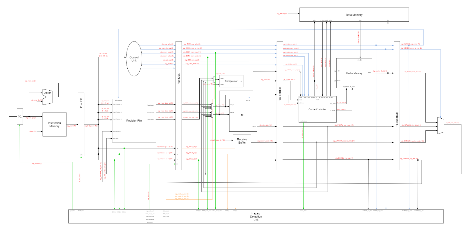 Pipelined Processor with cache memory for Real-time voting system
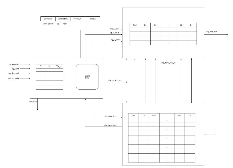 Cache memory and data memory
Key features
- The processor has 16-bit instructions which take in opcode,
rs,rt,rd. - The register file in this processor has 32 16-bit registers.
- The processor is a pipelined processor that has five stages:
IF,ID,EX,MEM,WB. - The processor has a network receive buffer to take in data from the testbench to simulate incoming network data.
- An ALU is present in the EX stage for arithmetic calculations.
- The system has a two-level memory hierarchy consisting of cache and data memory.
- A cache controller is implemented in the memory stage to control cache memory and data memory’s read/writes.
- A hazard control unit is implemented in this design to forward values with dependencies and stall program if cache has to read/write from/to data memory.
Design decisions and assumptions
- The number of candidates and districts are assumed to be 8 candidates and 15 districts.
- Rd is also readable for ST and SC. It is used to pass in the valid data value to specift the received data is valid.
- Checksum is used to authenticate data in order to mimic the use of network. It is calculated as adding all received values, including checksum, if the result is zero then the data is authenticated.
- The receive buffer takes in a 16-bit data from the TB and lets recv instruction to read in a 16-bit data as if it is received from the network. The TB inputs this value by reading a txt file provided in the sim directory. Only when recv is called will the TB read in a new value.
- Since we want the results to be stored as soon as possible for real-time updates, we want to directly access memory cells instead of calculating, therefore the districtID and CandidateID received from the network is directly used as the address. The data memory consists of 8 memory lines of 16 16-bit cells. The cache memory consists of 8 cache lines of 16 16-bit cells. The candidateID would be the index of blocks (and tag for cache memory) and the districtID would be the word select.
- Direct mapping is used for the cache design as there are small numbers of candidates.
- Data memory has two states: normal and stall. This is implemented to simulate the slow speed of memory and gives a p-clk penalty.
- The cache controller has four states: idle, ctag, wb, allocate. Idle is when there is no memory read/write instructions executing. Ctag is when cache compares tags for hits, if miss then go to wb if dirty bit is set, otherwise allocate the cache line.
- A hazard control unit is implemented to solve dependencies and LUHs. If a needed register is a write register that has not been written prior to the instruction, then the HCU forwards the value to the EX state (from MEM or WB). If the need register is to be written by cache data, then HCU would stall the processor by pumping nops into the IDEX stage until cache obtained data
Simulation results
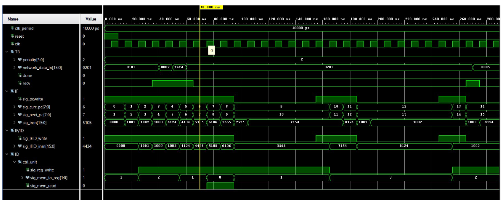
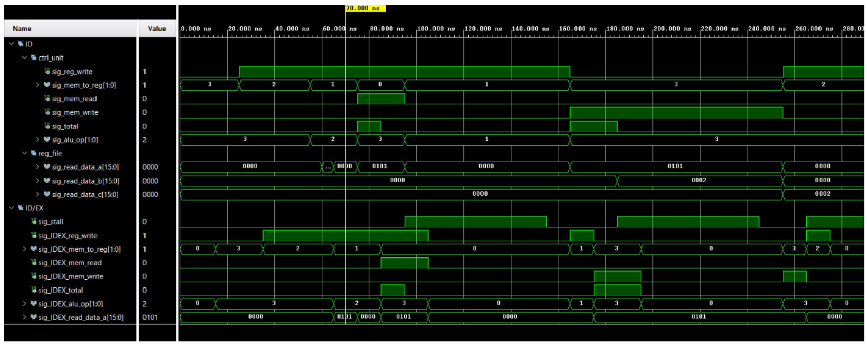
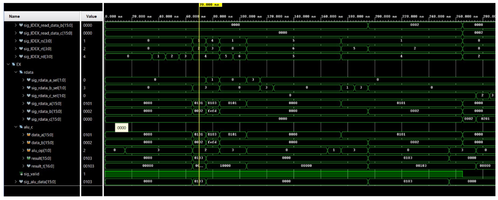
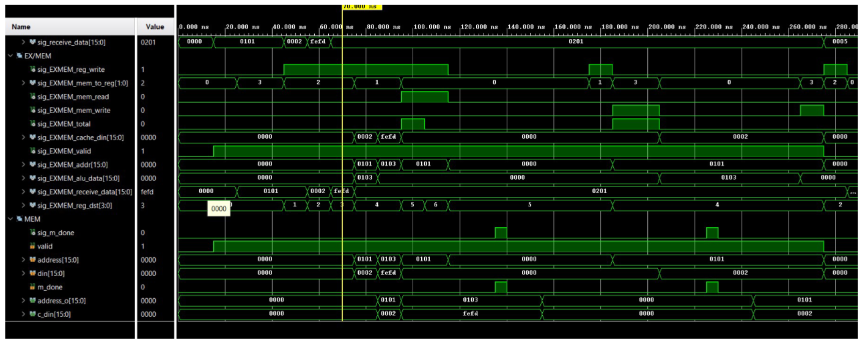
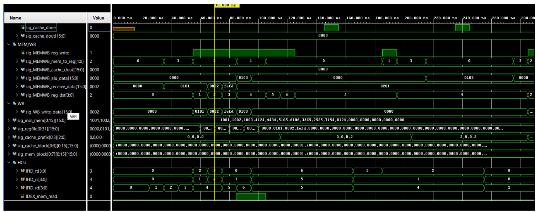
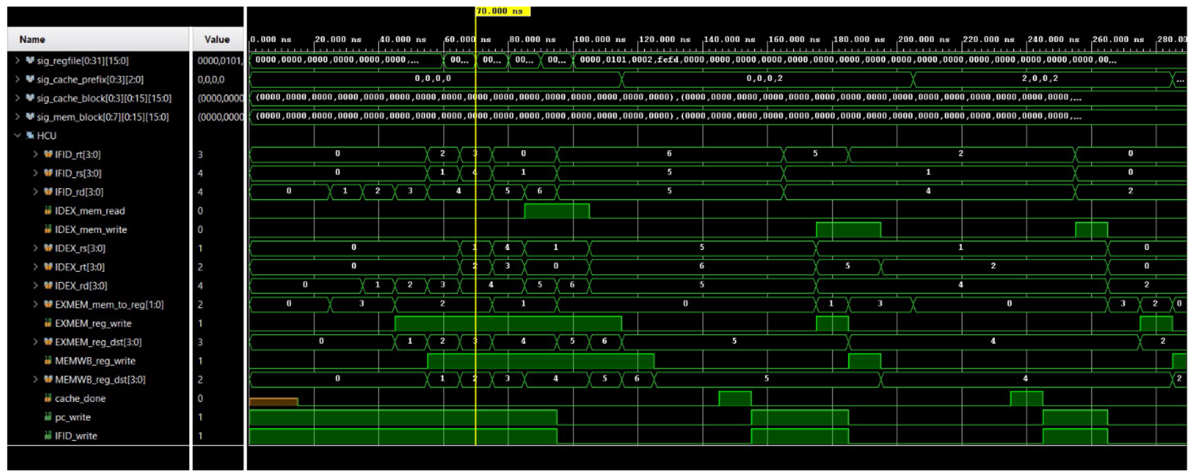
6 Simulation results and discussion (a) sim results 1 (b) sim results 2 (c) sim results 3 (d) sim results 4 (e) sim results 5 (f) sim results 6 Figure 3: Simulation results
As seen in the simulation results, the recv instruction obtains a 16-bit value three times which corresponds to D1D0, D32, and checksum. These three values does not stall the program as it does not access cache or data memory. The following two instructions add up the three values obtained from the receive buffer to calculate the checksum. These two also doesn’t stall the program. The next two however, would stall the program as it executes memory access. Since the first access would not find the data in cache as the program just started, it would have to reach to data memory to obtain the data, and thus cost a p-clk penalty. The next instruction, which is a LC instruction to the same candidate would not have the p-clk penalty as the previous access already allocated the memory block to the cache.
Overall, as the p-clk penalty increase, the use of a cache is much substantial as the avg acces time becomes:\
$1*hit+p*(1-hit)$